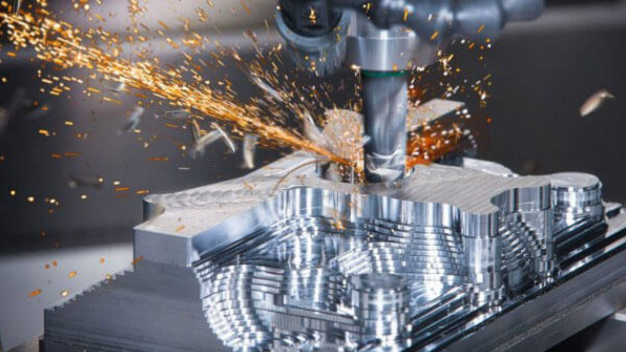
Technical drawings are essential to CNC machining because they act as a guide for accurate manufacturing. With the inclusion of crucial information like measurements, tolerances, and material specifications, these drawings serve as a visual guide. To program Computer Numerical Control (CNC) machines and ensure precise replication of complex components, machinists interpret these drawings.
Orthographic projections, material specifications, and Geometric Dimensioning and Tolerancing (GD&T) symbols are elements of a technical drawing. Using this data, CNC programmers create machine code that optimizes toolpaths for accurate and efficient material removal. The relationship between CNC machining and technical drawings highlights how crucial both processes are to creating unique, high-quality parts.
Fundamental Elements of a CNC Machining Technical Drawing
Technical drawings are essential for providing machinists and programmers with design information when using CNC (Computer Numerical Control) machining. These blueprints give the CNC machine a precise representation of the part that has to be machined and direct it through the manufacturing process. The following are the essential elements of a technical drawing intended for CNC machining:
Title Block:
Typically located at the bottom or right-hand corner of a technical drawing, the title block provides important details about the drawing itself. This contains the drawing’s title, the part’s name, the designer or engineer’s name, the creation date, and any pertinent revision information. The title block guarantees that important information is accessible to all parties involved in the manufacturing process and acts as a point of reference.
Section Views:
Part views are graphical depictions of an object that show off its many attributes and dimensions from various viewpoints. Front, top, side, and isometric views are common views. The distinct information provided by each view helps machinists comprehend the part’s overall geometry and structure. Dimension lines are usually included with these views to indicate the dimensions and positions of the features.
Dimensions:
The foundation of any technical drawing is correct dimensioning. The location, size, and form of features within the part are specified by the dimensions. They are essential to CNC machinists because they give the data needed to program the tools and make sure the finished product complies with the design specifications. To prevent confusion, dimensions should be arranged, labeled, and clearly defined.
Tolerances:
To guarantee that the finished product satisfies the necessary specifications, tolerances specify the permitted variations in dimensions. Tool wear and material variations are two examples of the many variables involved in CNC machining that could have an impact on the final product’s accuracy. Tolerances are crucial in determining the functionality and quality of the machined part. They are expressed using symbols and numerical values.
Material Specifications:
Details regarding the material to be used should be included in technical drawings for CNC machining. This covers the kind, grade, and any unique requirements for surface finish or heat treatment, among other things. To get the best results, machinists use this information to choose the right tools and machining parameters.
Surface Finish and Notes:
The texture and appearance of the machined surfaces are described in detail in the surface finish specifications. Specific surface finishes may be needed for certain applications; on the drawing, these details are indicated by symbols or numerical values. Notes may also be included to offer extra guidance or information that is essential to the machining process.
Geometric Adjustment:
A system for identifying and conveying acceptable variations in the shape, profile, orientation, and placement of features is known as geometric tolerancing. These tolerances are expressed using symbols like concentricity, perpendicularity, and true position. Particularly in applications involving precision machining, this element of technical drawings is crucial for guaranteeing the functional integrity of the finished product.
Bill of Materials (BOM):
A BOM is an exhaustive inventory of all the parts and sub-parts needed to assemble the finished product. Part numbers, descriptions, quantities, and occasionally extra details like suppliers are included. The manufacturing process is streamlined when a BOM is included in the technical drawing because it allows for effective communication between the production and design teams.
Bottom Lines
Technical drawings are essential tools that help the production and design teams communicate with each other smoothly when using CNC machining. Precise and accurate manufacturing is ensured by the careful inclusion of dimensions, tolerances, material specifications, and other important details. These drawings act as a blueprint, effectively and dependably converting design intent into tangible, high-quality products.
